With regards to these diagrams its important to note that the black dots represented in the first diagram (see at the bottom of page) means that the wires are connected.
For information sake, when a wire is depicted in a diagram that it looks like its hopping over it means that theyre not connected in real life.
To connect a wire as shown in the diagram, you can cut and splice or use 3M Scotchlok connectors that crimp onto the wire to make a connection.
Alternatively, you can strip back the insulation and wrap the other wire around it and solder the connection with electrical tape or heat shrink tubing. You can also use wire nuts to secure the connection, crimp caps or terminal strips.
These are thanks to PTCruzr!!!
Neon Accent Tube Wiring Diagram #1 (for neons WITHOUT external transformer). NOTE: If using a light up switch connect the 3rd connection on the switch to ground.
Neon Accent Tube Wiring Diagram #2 (for neons WITH external transformer). NOTE: If using a light up switch connect the 3rd connection on the switch to ground.
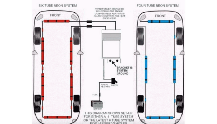
Neon Underbody Kit Diagram #1 (for kits WITHOUT an external transformer). NOTE: If using a light up switch connect the 3rd connection on the switch to ground.
Neon Underbody Kit Diagram #2 (for kits WITH an external transformer). NOTE: If using a light up switch connect the 3rd connection on the switch to ground
Neon Washer Nozzles Diagram NOTE: If using a light up switch connect the 3rd connection on the switch to ground.
Neon Pedals Diagram Neon Pedals Diagram
EL Wire Diagram NOTE: If using a light up switch connect the 3rd connection on the switch to ground.
LED Wiring Diagram Notice the load resistor that IS needed. Also notice that the Anode on the LED is connected to positive. The Anode is the LONGER lead. NOTE: If using a light up switch connect the 3rd connection on the switch to ground
Similar LED Wiring Diagram Heres a similar LED wiring diagram showing 4 seperate LEDs (NOT connected). Notice the load resistor that IS needed for each LED. Also notice that the Anode on the LED is connected to positive. The Anode is the LONGER lead. NOTE: If using a light up switch connect the 3rd connection on the switch to ground.
Multiple LEDs Wiring Diagram Notice that NO load resistor is needed. Also notice the Anode and Cathode connections. The Anode is the LONGER lead. The LEDs MUST be connected in series, NOT in parallel. NOTE: If using a light up switch connect the 3rd connection on the switch to ground
12 LEDs Wiring Diagram Notice that NO load resistor is needed. Also notice the Anode and Cathode connections. The Anode is the LONGER lead. The LEDs MUST be connected in series, NOT in parallel. NOTE: If using a light up switch connect the 3rd connection on the switch to ground